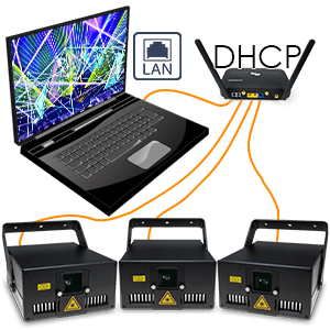
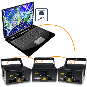
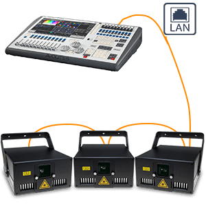
How to connect multiple laser systems to the computer with using a Router or another DHCP capable system
These instructions are ONLY suitable, if the lasers are connected to the computer with a DHCP capable device, like a router or a wifi access point with DHCP feature. If a DHCP server is in the same network, the Auto-IP functionality does not work, as it's blocked out by the DHCP and overridden.
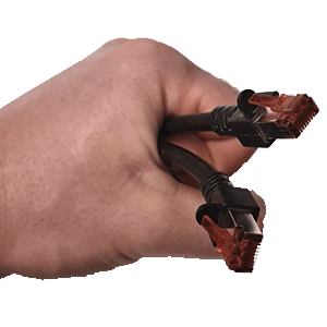
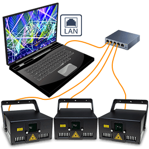
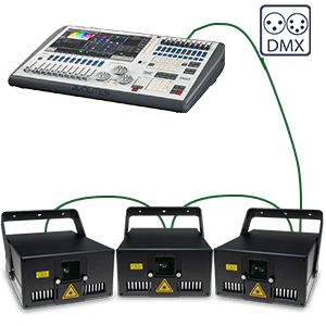
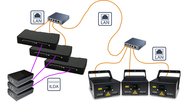
1. Use standard LAN-cable (Ethernet-cable), minimum of standard CAT-5 (most cables are), and connect the LAN interface of each laser ...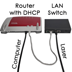
2. ... to the router. Any standard, modern router is suitable, if it has a DHCP fuctionality.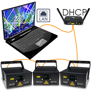
3. Depending on the Laser system it can also be possible to daisy-chain the LAN signal in DHCP mode, if there is at least one DHCP somewhere in the network ...
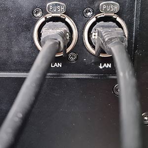
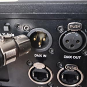
4. ... if the Laser has two or more LAN connectors.
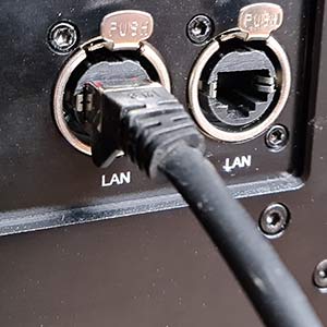
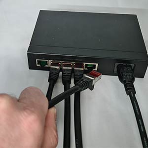
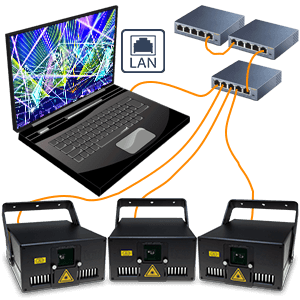
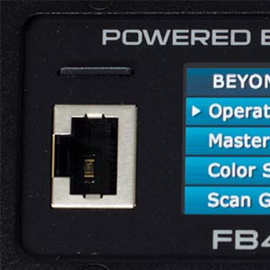
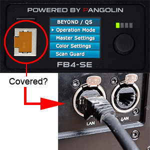
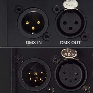
5. Make sure to use the correct ports (usually marked as LAN / computer / ShowNET / Control or similar).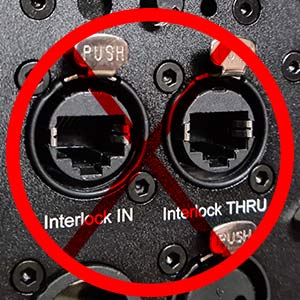
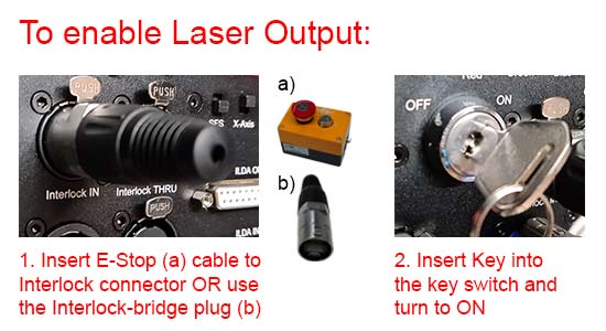
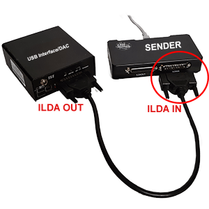
6. Do NOT plug the signal cables into the Interlock port!
Interlock is only for the E-Stop or the Interlock-bridge plug!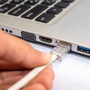
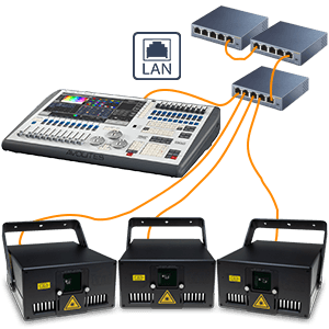
7. Connect the network switch to the computer using a LAN cable.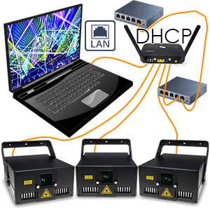
8. The setup can easily be extended by using more switches in the network to distribute the signal. Just remember: only ONE router with DHCP per network. The rest must be normal switches without DHCP functionality.
Connection scheme:
1. Use standard LAN-cable (Ethernet-cable), minimum of standard CAT-5 (most cables are), and connect the LAN interface of each laser ...
2. ... to the router. Any standard, modern router is suitable, if it has a DHCP fuctionality.
3. Depending on the Laser system it can also be possible to daisy-chain the LAN signal in DHCP mode, if there is at least one DHCP somewhere in the network ...
4. ... if the Laser has two or more LAN connectors.
5. Make sure to use the correct ports (usually marked as LAN / computer / ShowNET / Control or similar).
6. Do NOT plug the signal cables into the Interlock port!
Interlock is only for the E-Stop or the Interlock-bridge plug!
7. Connect the network switch to the computer using a LAN cable.
8. The setup can easily be extended by using more switches in the network to distribute the signal. Just remember: only ONE router with DHCP per network. The rest must be normal switches without DHCP functionality.
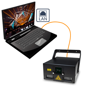
A. Connect with Address distribution by DHCP (recommended in combination with a router)
DHCP is an automated address handling system that assigns an address to each network device in the same environment. This is commonly used in home and corporate networks to ease the network address asignment process. It requires a DHCP server to be present in the network. Usually the router or Wifi access point can do this task.
In most cases the user does not have to configure anything for using network devices in a DHCP environment.
If the laser shall be operated in an existing network that has a DHCP present, it can be set to "Auto-IP" operation mode to automatically obtain an address from the DHCP. When enabled, the FB4 will search for a DHCP server and when none is found it will allow for generation of an "Auto-IP" address.
If the settings of the computer have been changed or are non-standard, follow these instructions to reset it back to automatic address negotiation. You usually can skip this if you have no idea or haven't changed anything.
In most cases the user does not have to configure anything for using network devices in a DHCP environment.
If the laser shall be operated in an existing network that has a DHCP present, it can be set to "Auto-IP" operation mode to automatically obtain an address from the DHCP. When enabled, the FB4 will search for a DHCP server and when none is found it will allow for generation of an "Auto-IP" address.
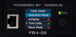
- Configure the network operation mode:
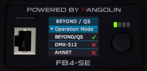
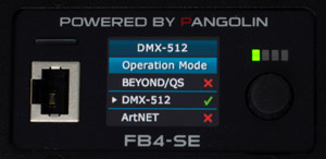
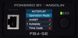
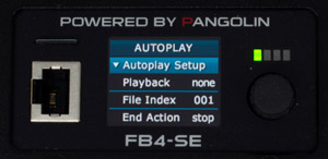
Turn the selection rotary dial until the cursor points to the menu item "Operation mode" and press it once to expand the menu options: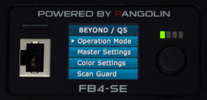
- Turn the rotary dial until the cursor points to the desired operating mode (Beyond/QS) and press it once. The selected operation mode (Beyond/QS) is now active:
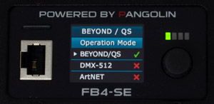
- Turn the selection rotary dial until the cursor points to the menu item "Operation mode" and press it to close the menu item.
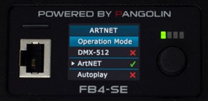
- Turn the selection rotary dial until the cursor points to the menu item "Network Setup" and press it to expand the menu item:
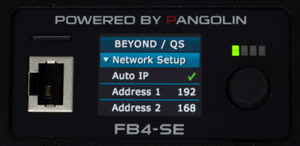
- Turn the rotary dial until the cursor points to "Auto IP".
- Press the rotary dialonce. The selected network mode (Auto IP) is now active.
- Turn the selection rotary dial until the cursor points to the menu item "Network Setup" and press it to close the menu item.
- Turn the selection rotary dial until the cursor points to the menu item "Exit Menu" and press it to save all settings and values on the SD card.
If the settings of the computer have been changed or are non-standard, follow these instructions to reset it back to automatic address negotiation. You usually can skip this if you have no idea or haven't changed anything.
 How to set the computer to Auto-IP addressing
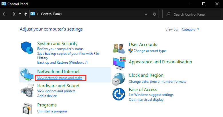
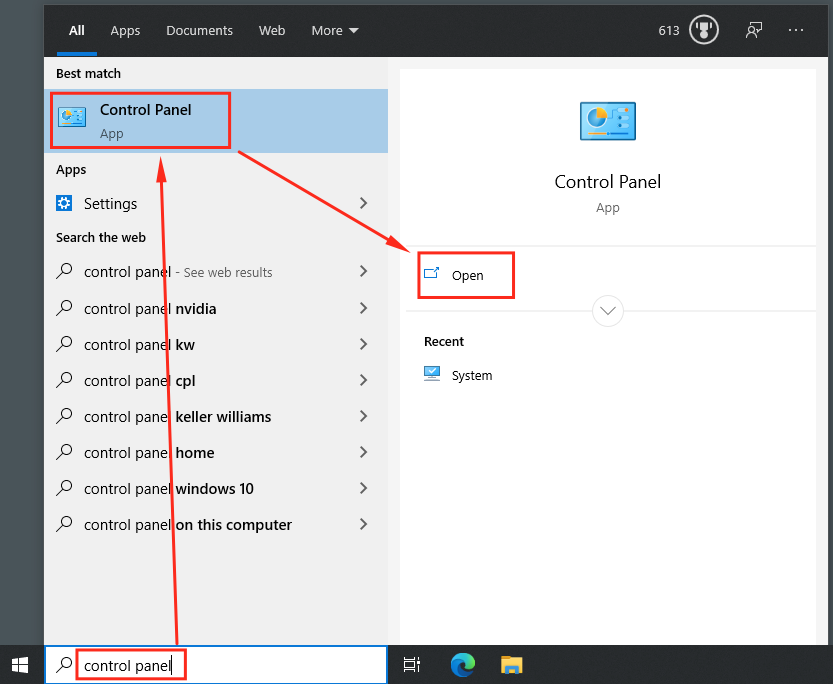
- Press the Windows-key and type "control panel" (without quotes; this can also be done througn the search bar) > Click on "Control Panel" > Click on Open.

- Click on "View network status and tasks" under "Network & Internet".
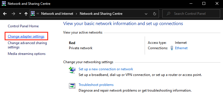
- Click on "Change adapter settings"

- Right click the network adapter > Click on "Properties".
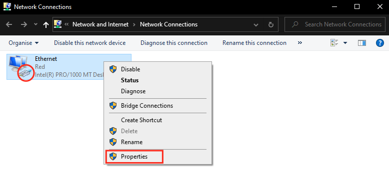
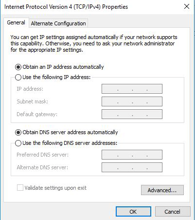
If there are multiple icons in this window, the correct one is usually labeled with "ethernet". It also should have the little network connector icon. Note that it may also have a red "X" if it's disconnected or not properly configured. - Select the Internet Protocol Version 4 (TCP/IPv4) option > click the "Properties button".
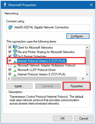
- Select "Obtain an IP address automatically" to let the computer automatically negotiate the IP address.
B. Connect via Static IP (manual configuration mode)
It often makes sense to work with permanent, specifically assigned identifiers per laser in a production environment. The Laser mainboard can be assigned a static IP address to avoid address changes when the network infrastructure is altered. There is no general advantage over the use of Auto IP or DHCP, but sometimes users prefer to use a static IP.
What's an IP address?
Any device connected to a network environment, such as computers, printers, smartphones and also lasers, no matter if it's a wired connection or wifi network, has a unique identification number. This unique address is the so called IP address.
The IP address type used for the communication with the laser systems consists of a group of 4 numbers (each between 0 and 255), separed by a point (".") symbol. It looks like this:
www.xxx.yyy.zzz
Schematics example of an IP/v4 address:
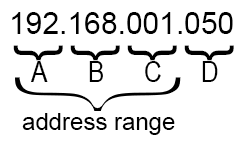
If devices shall communicate with each other, they need to reside in the same address range, which means that the first 3 numbers must be the same. The fourth number, however, must be unique for each device in the network.
In a home or office environment the computers and hardware components usually get these addresses assigned automatically by the so called DHCP server, which included in the utmost of routers or wifi access points. That's why it is usually not necessary to take care of setting these addresses manually. However, if there is no DHCP server available, the devices in a network either need to negotiate the suitable addresses for each device between each other (so called Auto IP) or they requrie static IP addresses the be manually set.
As there is usually no DHCP available at show production sites, laser show settings may require either Auto IP setting or static IP.
Show production companies tend to use static IPs, as then the address distribution does not depend on any additional communication between the devices in the network and each unit can be checked on more specifically through the network and various tools.
The IP address type used for the communication with the laser systems consists of a group of 4 numbers (each between 0 and 255), separed by a point (".") symbol. It looks like this:
www.xxx.yyy.zzz
Schematics example of an IP/v4 address:
If devices shall communicate with each other, they need to reside in the same address range, which means that the first 3 numbers must be the same. The fourth number, however, must be unique for each device in the network.
In a home or office environment the computers and hardware components usually get these addresses assigned automatically by the so called DHCP server, which included in the utmost of routers or wifi access points. That's why it is usually not necessary to take care of setting these addresses manually. However, if there is no DHCP server available, the devices in a network either need to negotiate the suitable addresses for each device between each other (so called Auto IP) or they requrie static IP addresses the be manually set.
As there is usually no DHCP available at show production sites, laser show settings may require either Auto IP setting or static IP.
Show production companies tend to use static IPs, as then the address distribution does not depend on any additional communication between the devices in the network and each unit can be checked on more specifically through the network and various tools.
What is an IP address and how does it work:
Schematics of an IP/v4 address:
Each laser must be given a different IP address in the same IP address range (see scheme above). Never give the same IP address to different devices in one network!
This also applies for the computer: The IP address assigned to the computer MUST have a different ending ("D" in the Schematics) than any of the lasers.
Attention! If a WiFi connection is used on the computer at the same time as the laser control, make sure that the address range (the first part A,B,C; see schematics) is different to the range that is used for the lasers. Determine IP addresses if Wifi and laser control shall work at the same timeTo check on the IP addresses, click on the Wifi network icon in the taskbar > click the Wifi network you're connected to > Properties.
In Properties, look for the IP address listed next to IPv4 address.
Note: The first 3 numbers of the IP address (the address range, see schematcs) must be different for the wired connection to the laser. For example:- Computer's Wifi has an IP of 192.168.0.X -> use any IP like 192.168.1.X or 192.168.2.X or 192.168.254.X
- Computer's Wifi has an IP of 192.168.1.X -> use any IP like 192.168.0.X or 192.168.2.X or 192.168.254.X
- Computer's Wifi has an IP of 192.168.2.X -> use any IP like 192.168.0.X or 192.168.1.X or 192.168.254.X
- Computer's Wifi has an IP of 192.168.254.X -> use any IP like 192.168.0.X or 192.168.1.X or 192.168.2.X
- Computer's Wifi has an IP of any other number different that 192.168.X.Y -> use any IP like 192.168.0.X or 192.168.1.X
Specify the IP address
Parts "A", "B" & "C" (see schematics) must be the same number for all devices, lasers and computer, that shall communicate in the same network.
In order to prevent issues with internet connection, some address are reserved for internal use (as in this case), so you must setup your network in a proper way:- range 192.168.XXX.YYY:
- XXX: any number from 1 to 254 - remember that it needs to be the same in all your devices!
- YYY: any number from 1 to 254 - remember that it needs to be different for all your devices!
- range 10.WWW.XXX.YYY:
- WWW: any number from 1 to 254 - remember that it needs to be the same in all your devices!
- XXX: any number from 1 to 254 - remember that it needs to be the same in all your devices!
- YYY: any number from 1 to 254 - remember that it needs to be different for all your devices!
- range 192.168.XXX.YYY:
Set the IP address at the Laser
Set the Display to Static IP configuration using the rotary dial:- Configure the network operation mode:
Turn the selection rotary dial until the cursor points to the menu item "Operation mode" and press it once to expand the menu options: - Turn the rotary dial until the cursor points to the desired operating mode (Beyond/QS) and press it once. The selected operation mode (Beyond/QS) is now active:
- Turn the selection rotary dial until the cursor points to the menu item "Operation mode" and press it to close the menu item.
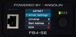
- Turn the selection rotary dial until the cursor points to the menu item "Network Setup" and press it to expand the menu item:
- Turn the rotary dial until the cursor points to "Address 1". This allows you to change the first part of the IP address (Part "A").
- Press the rotary dialonce to select, then rotate it to select the number you chose as Part "A" of the device IP address, and press the rotary dial again to validate it.
- Below "Address 1" you can find the settings for the rest of the IP address values.
Repeat previous step to set up its value, having count that:- "Address 2" relates to Part "B"
- "Address 3" relates to Part "C"
- "Address 4" relates to Part "D"
- Turn the rotary dial until the cursor points to "Mask 1":
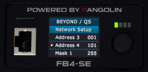
- Press the rotary dialonce to select, then rotate it to select number 255, and press the rotary dial again to validate it.
- Below "Mask 1" you can find the settings for the rest of the IP address values.
Repeat previous step to set up its value, having count that:- "Mask 2" must have value 255
- "Mask 3" must have value 255
- "Mask 4" must have value 0
- Turn the selection rotary dial until the cursor points to the menu item "Network Setup" and press it to close the menu item.
- Turn the selection rotary dial until the cursor points to the menu item "Exit Menu" and press it to save all settings and values on the SD card.
- Configure the network operation mode:
Configure the IP address for the computer
The computer also requires to be set to a static IP address if the lasers use one. Make sure to specify an address in the same address range, but with a different address ("D" in the schematics) than any of the lasers.
If the whole IP address of the computer and any of the lasers is identical, it will NOT work - they MUST be different in "D", but identical for "A","B" and "C" (referring to above schematics).
Read the how-to guide below for details on how a static IP can be set How to configure a static IP address for a computer - Press the Windows-key and type "control panel" (without quotes; this can also be done througn the search bar) > Click on "Control Panel" > Click on Open.
- Click on "View network status and tasks" under "Network & Internet".

- Click on "Change adapter settings"
- Right click the network adapter the laser is connected to > Click on "Properties".

If there are multiple icons in this window, the correct one should be labeled "ethernet"; it usually has the little network connector icon. Note that it may also have a red "X" if it's disconnected or not properly configured. - Select the Internet Protocol Version 4 (TCP/IPv4) option > Click "Properties button".

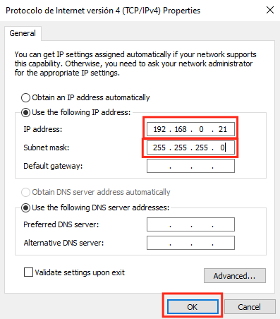
- In this windows the configuration happens:
- Write the desired IP address for the computer to the "IP address" box (i.e. 192.168.0.21).
- Write "255.255.255.0" (without quotes) to the "Subnet mask" box.
- Click "OK" button.
- Press the Windows-key and type "control panel" (without quotes; this can also be done througn the search bar) > Click on "Control Panel" > Click on Open.


Distributed brands: