

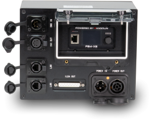


How is the ILDA connector pinout?
A common interface is used in showlaser industry to operate laser projectors by computer control. As interface the DB-25 connector is used, as the signal transmission is done in a parallel transmission. The signal transmission itself does not use a modern protocol type, like used e.g. in ethernet networks or other serial transmission types, but it is a very low-level transmission that only modulates the voltage on every pin - usually in a range of 5V difference (-2.5V - +2.5V or 0V - 5V).
This so called "ILDA connection" is a rather old transmission method, however it is used for nearly all computer controllable laser systems at the moment.
As the ILDA signal is a parallel transmission, the computer control signal (which is serial) needs to be converted to ILDA. This is done by the so called DAC (Digital Analogue Converter), which is also called "USB Interface" or "USB box" in combination with laser software. The parallel signal can only transmit one type of signal. It is not possible to address different lasers and give them individual control signals with one DAC. Do do so, you need additional DACs (one for each laser that should be controlled individually). However, the same ILDA signal can be used by many laser projectors - but they would do all the same.
To reduce the need of DACs, we suggest to link the ILDA signal of some projectors. Please see our setup suggestions for details: Installation & Setup FAQ
The ILDA connector has the following pinout:
| Pin 1 | x-axis scanner, positive signal. Difference of 10V |
| Pin 2 | y-axis scanner, positive signal. Difference of 10V |
| Pin 3 | intensity/brightness, positive signal. Difference of 5V |
| Pins 4 and 17 | Interlock. Linking of both enables output |
| Pin 5 | red intensity, positive signal. Difference of 5V |
| Pin 6 | green intensity, positive signal. Difference of 5V |
| Pin 7 | blue intensity, positive signal. Difference of 5V |
| Pin 8 | deep blue intensity, positive signal. Difference of 5V |
| Pin 9 | yellow intensity, positive signal. Difference of 5V |
| Pin 10 | cyan intensity, positive signal. Difference of 5V OR: DMX512 IN; positive signal (Showeditor and Phoenix interfaces). |
| Pin 11 | DMX512 OUT; positive signal (Showeditor and Phoenix interfaces). |
| Pin 12 | Projector return signal |
| Pin 13 | Shutter. Difference of 5V |
| Pin 14 | x-axis scanner, negative signal. Difference of 10V |
| Pin 15 | y-axis scanner, negative signal. Difference of 10V |
| Pin 16 | intensity/brightness, negative signal. Difference of 5V |
| Pins 17 and 4 | Interlock. Linking of both enables output |
| Pin 18 | red intensity, negative signal. Difference of 5V |
| Pin 19 | green intensity, negative signal. Difference of 5V |
| Pin 20 | blue intensity, negative signal. Difference of 5V |
| Pin 21 | deep blue intensity, negative signal. Difference of 5V |
| Pin 22 | yellow intensity, negative signal. Difference of 5V |
| Pin 23 | cyan intensity, negative signal. Difference of 5V OR: DMX512 IN; negative signal (Showeditor and Phoenix interfaces) |
| Pin 24 | DMX512 OUT; negative signal (Showeditor and Phoenix interfaces). |
| Pin 25 | Ground |